Case note · Turning + 3+2 milling · October 2026

SUS430 motor housings held to 0.01 mm

An overseas customer ordered 100 small motor housings in SUS430 stainless. The drawing called for two diameters with tolerance bands of 10 and 15 µm, 0.01 mm concentricity to the bore, cross pins pressed in, and a bead-blasted finish that must not touch the pins.

Material
SUS430 stainless
Quantity
100 pcs
Part
Motor housing
Tightest band
10 µm on Ø8
Concentricity
Ø0.01 mm to A
Process
Turning + 3+2
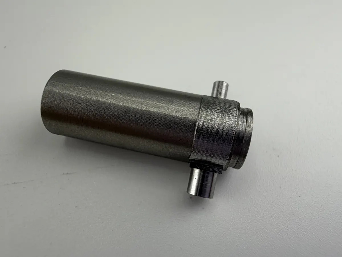
Turned SUS430 stainless motor housing with pressed-in cross pins
One of the 100 finished housings, about Ø8 mm. Drawing and customer details are not shown.
The problem

A small part with almost no room for error

  • 10 µm bands. The Ø8 diameter had to sit between 7.980 and 7.990 mm, and the Ø7 step between 6.995 and 7.010 mm.
  • Everything tied to the bore. Concentricity and circularity of 0.01 mm meant the outside, the steps, and the cross holes all had to follow one axis.
  • Cross holes after turning. Ø3 and Ø0.8 mm cross holes had to line up with that axis on a part too small to clamp by its outside without marking it.
  • Blast everything except the pins. The housing is bead blasted; the pressed-in pins are not.
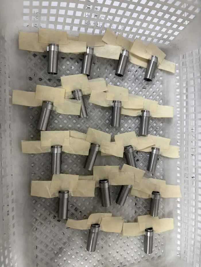
Batch of SUS430 motor housings laid out and taped one by one
Part of the 100-piece batch, laid out and taped one by one.
Step 1 · Turning

Diameters and bore turned first

The outside diameters, the steps, and the bore are turned on the lathe first. The turned bore becomes the datum for every operation after it.

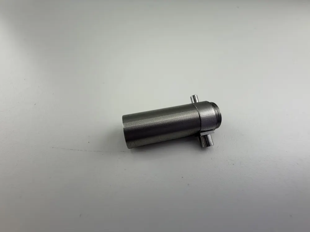
Turned SUS430 motor housing showing the outside diameters and steps
The turned housing: outside diameters, steps, and bore on one axis.
Step 2 · Cross holes on a mandrel

A mandrel that locates on the bore

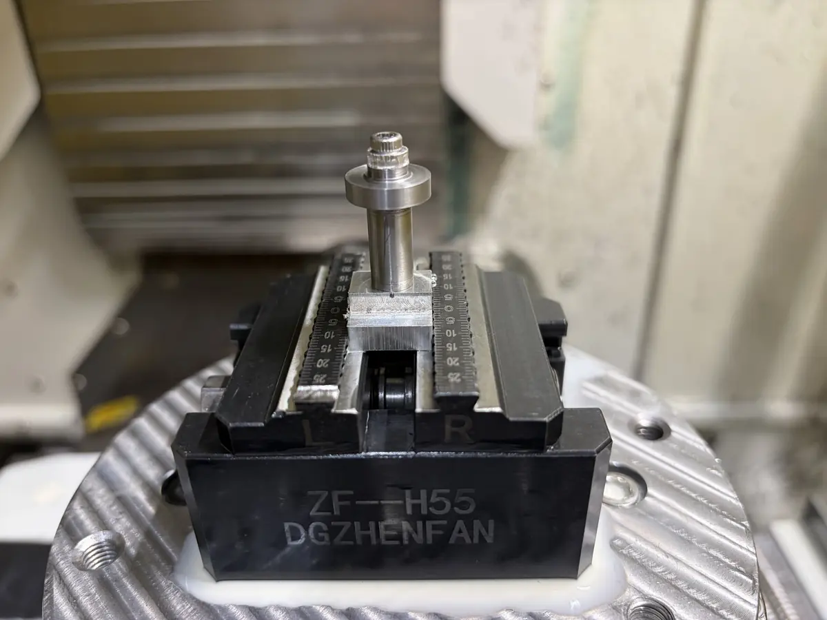
For the cross holes, each housing slides onto a dedicated mandrel held in a zero-point vise on the rotary table of a 3+2 machining center. The mandrel locates on the turned bore, so the cross holes are cut relative to the same axis as the diameters.

The zero-point vise lets the fixture come off and go back on in the same position, so a repeat batch starts without re-indicating.

Loading a housing onto the mandrel. Real footage, October 2026.
Step 3 · Pins and finish

Pins pressed in, everything but the pins blasted

The cross pins are pressed in after milling. The housing is then bead blasted, with the pin surfaces left unblasted as the drawing requires.

Housing on its mandrel fixture in a zero-point vise on the rotary table
The mandrel fixture in the zero-point vise on the rotary table.
Inspection

Measured part by part with a micrometer

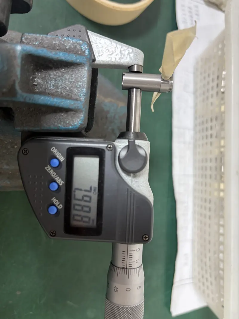
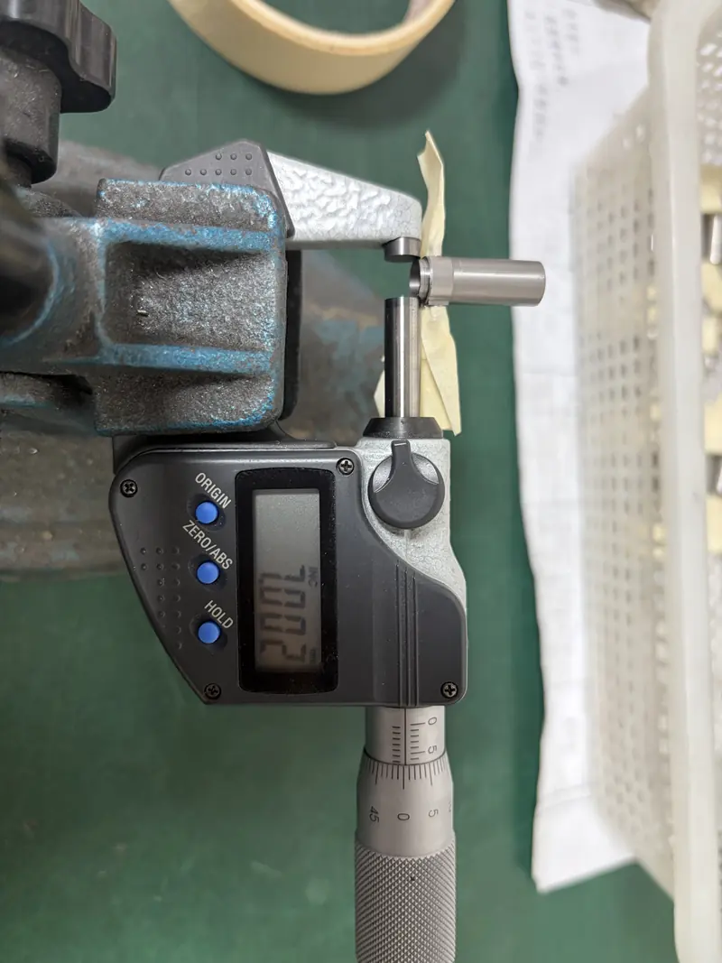
Every housing was measured on the critical diameters before packing. These are readings from the photos on this page:

FeatureDrawingAllowed rangeMeasured
Ø8 outside8 −0.01 / −0.027.980 – 7.9907.987OK
Ø8 outside8 −0.01 / −0.027.980 – 7.9907.988OK
Ø7 step7 +0.01 / −0.0056.995 – 7.0107.002OK

All 100 housings were packed for export. More parts from recent orders →

Digital micrometer reading 7.988 mm on the Ø8 diameter of a motor housing Digital micrometer reading 7.002 mm on the Ø7 step of a motor housing
For your drawing

Designing a small precision housing?

Three things that make parts like this faster to quote and easier to hold.

Mark the datum bore

Tell us which bore or diameter the part locates on. We build the fixture around it, so concentricity is held by the setup, not by luck.

Say where finish must not go

A note like "pin surfaces not blasted" saves a question and a rework. Mark it on the drawing, as this customer did.

Order enough for a fixture

A dedicated mandrel pays for itself from about 20 pieces, and unit cost drops sharply from there.

Have a small part with micron tolerances?

Send the drawing. We'll tell you how we would hold and measure it, and quote it with DFM notes. Email reply within 24 hours.

Send Your Drawing CNC turning