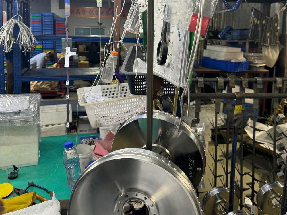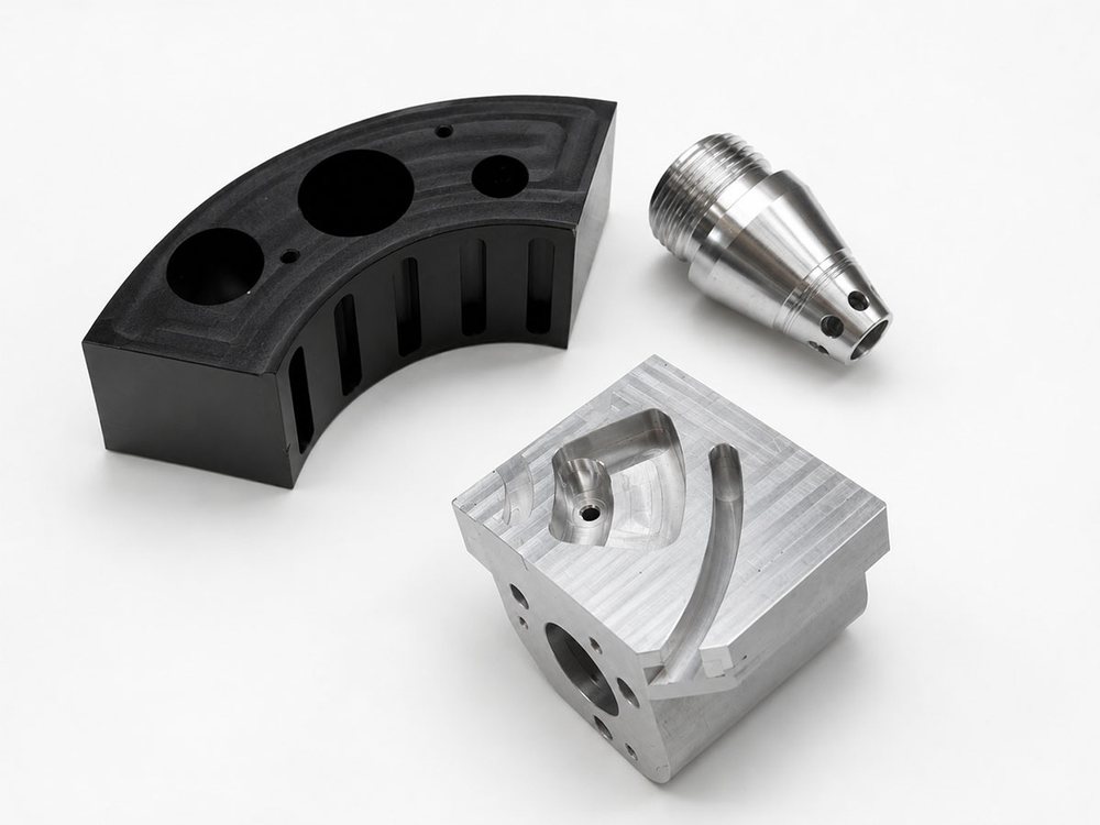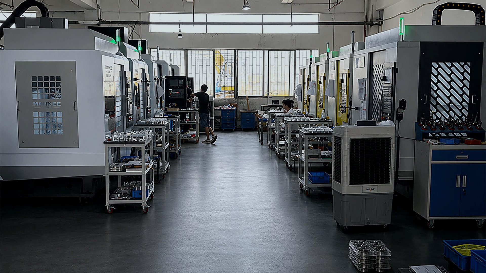
CNC machining workshop at Meili Machining, Dongguan, China
CNC Machining Services · Dongguan, China

CNC Machining
from Dongguan,
China

About 23 CNC milling machines and lathes supporting prototype, low-volume, and small-to-medium batch parts. Send drawings for engineering review, machining feasibility feedback, and a clear quote after drawing review.

Dongguan Location · Since 2017
~23 CNC milling machines & lathes
1000 × 400 × 200 mm Max milling size
approximately Ø400 × 900 mm Max turning size
drawing review Quote response (standard RFQ)
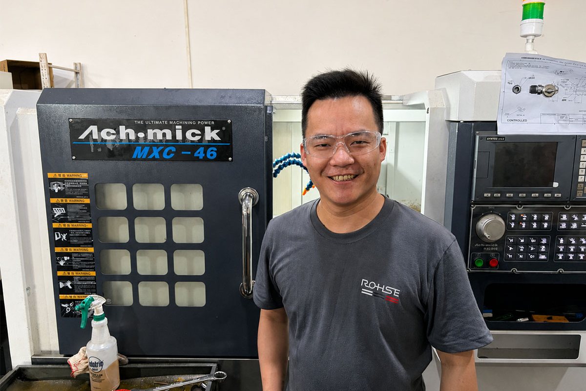
about 23 CNC machines and lathes in-house Common metals, plastics & finishes reviewed before quote Drawing-based RFQ review Inspection reports available on request
Who this is for

Best fit for drawings
that need more than a quick price

Meili is a practical choice when the project involves more than commodity parts at the lowest unit cost. We are set up to handle drawing review, tolerance discussion, machining plus finishing coordination, and inspection method confirmation before production starts.

Not the best fit for: price-only commodity parts, projects without drawings or specifications, or regulated parts requiring certifications we do not hold.
CNC machines at Meili Machining workshop, Dongguan
What we do

CNC machining processes
available from one team

All processes are coordinated in-house or through managed partners. You send one drawing set — we handle the process planning.

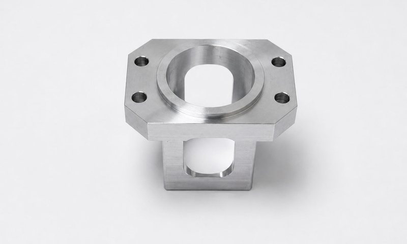
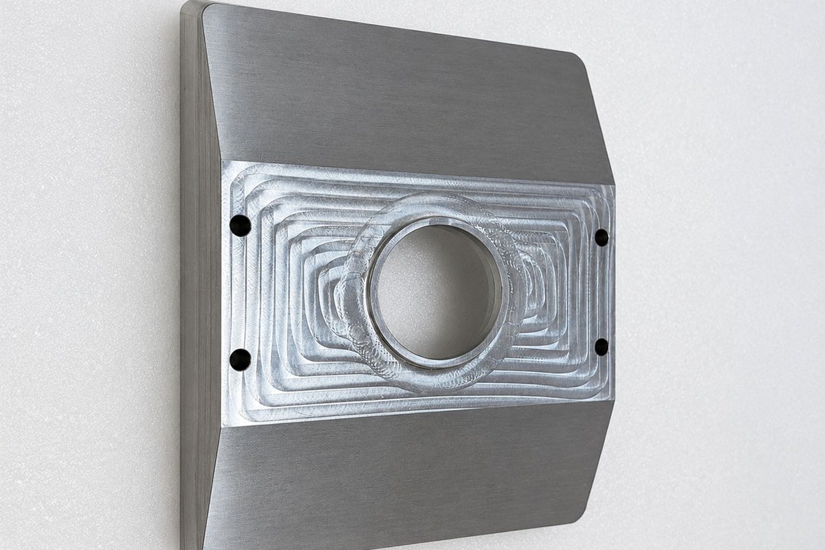
CNC milled precision parts

CNC Milling

3-axis & 3+2

Flat faces, pockets, contours, slots, and multi-face features. About 10 three-axis and about 5 3+2 multi-face machining centers support prototypes through small-batch production.

CNC Milling details
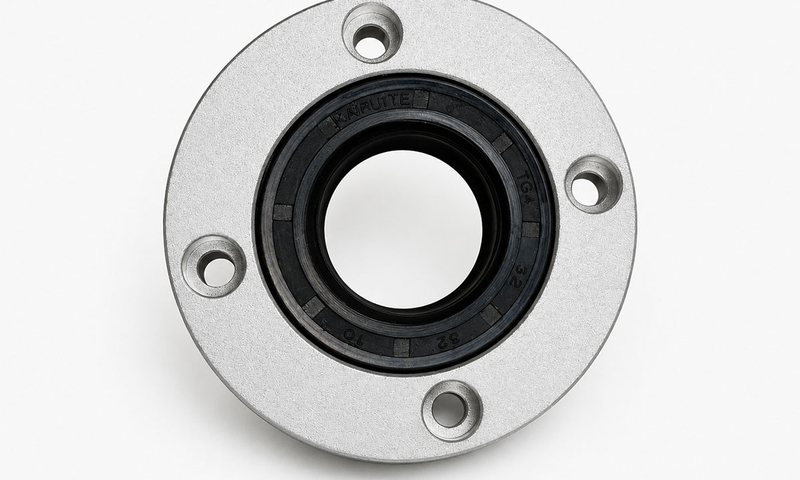
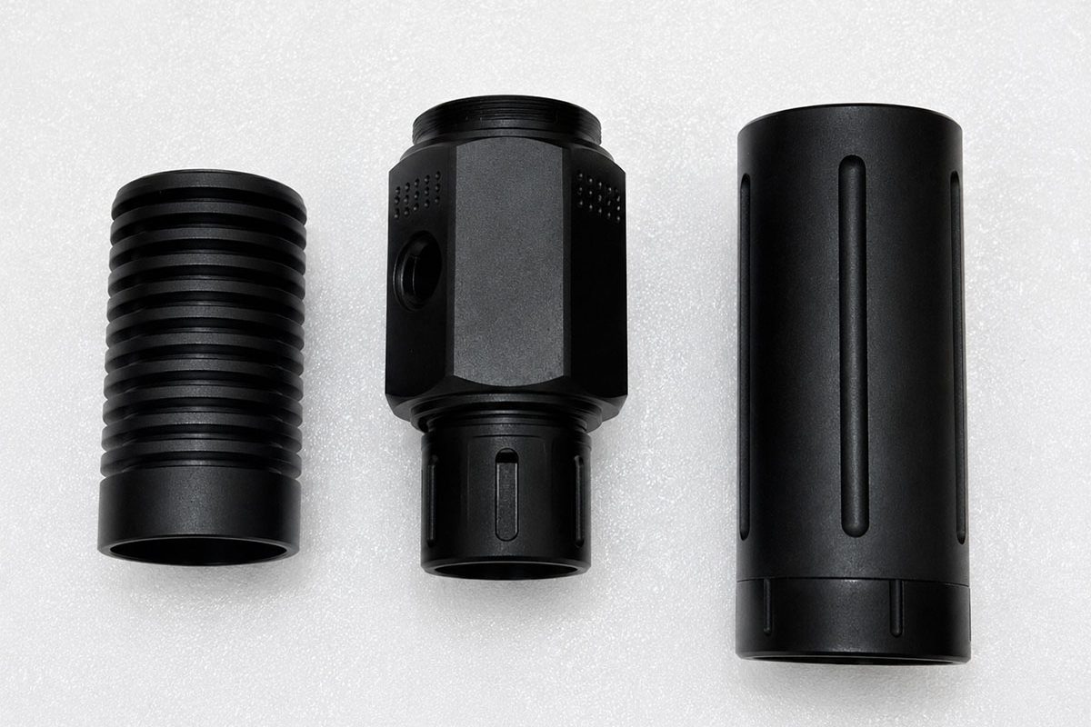
CNC turned shafts and round components

CNC Turning

about 8 CNC lathes

Shafts, sleeves, pins, bushings, and threaded components approximately Ø400 × 900 mm. Secondary milling features can be added in one setup.

CNC Turning details
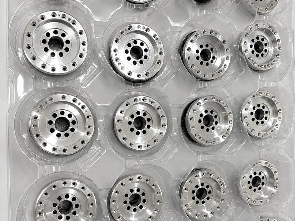
Multi-face CNC machined parts from 3+2 machining centers

3+2 Multi-face Machining

Current capacity — B + C axis

Multi-face parts handled through 3+2 process planning — B and C axis positioning. Suitable for angled holes, compound features, and parts requiring multi-face work. The process route is confirmed after drawing review.

Ask about your geometry →
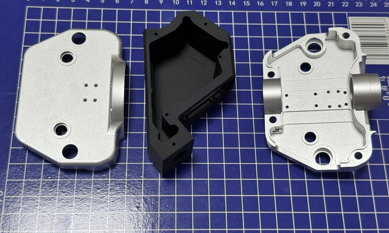
Anodized and surface-finished CNC machined parts

Secondary Processes

Coordinated partners

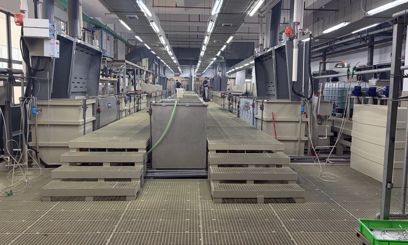
Anodizing, plating, heat treatment, EDM, laser marking, and deburring arranged through managed partners. Single contact for machining through finishing.

Secondary processes
Equipment

Real CNC capacity
in Dongguan

About 23 CNC milling machines and lathes, forming our core in-house machining capacity. The mix of three-axis and 3+2 machining centers, combined with CNC lathes, allows us to handle multi-face parts, turned components with milled features, and small-to-medium production batches in the same facility.

~10
Three-axis CNC milling machines
~5
3+2 multi-face machining centers
~8
CNC lathes
~23
CNC machines and lathes
1000 × 400 × 200
Max milling size (mm)
approximately Ø400 × 900
Max turning size (mm)
3+2 multi-face machining: B and C axes position and lock the part before three-axis cutting. For complex geometry, we review the drawing and confirm the feasible process route before quoting.
3+2 CNC machining centers at Meili Machining, Dongguan
Process
  • 3-axis and 3+2 positioning in-house
  • CNC turning approximately Ø400 × 900 mm
  • Drawing review before every quote
  • Multi-face geometry confirmed before production
  • Prototype to small-batch production
Tolerance Range
Milling std ±0.05 mm
Turning std ±0.02 mm
Critical dims ±0.01 mm
Surface Ra 0.8–3.2 μm
CNC turned shafts, sleeves, and round components
Materials

Common materials
we machine regularly

Material selection depends on your drawing requirements, application environment, and finishing. If your specific grade is not listed, ask — we can usually confirm availability before quoting.

Grade confirmation is part of every drawing review. If you specify a grade we do not regularly stock, we confirm lead time and availability before accepting the order.
6061-T6
Brackets, housings, frames, fixtures
Anodizing (Type II / III), bead blast
Most common grade. Specify anodize tolerance separately — adds 0.01–0.025 mm per side.
7075-T6
Load-bearing structural parts, jigs
Anodizing (Type II), bead blast
Higher strength. Not recommended for welding. Slower feeds than 6061.
2024-T3
High-fatigue structural applications
Anodizing, chromate conversion
Surface protection usually required — more corrosion-prone than 6061.
5052
Sheet metal enclosures, brackets
Anodizing, powder coat
Better for forming and bending than machining from billet.
303
Shafts, fasteners, connectors
Passivation, bead blast
Easiest stainless to machine. Not weldable — switch to 304 if welding needed.
304 / 304L
Enclosures, food equipment, general industrial
Passivation, electropolish, bead blast
Work-hardens quickly. Specify passivation requirement on drawing.
316 / 316L
Marine, chemical, instrument components
Passivation, electropolish
Better chloride resistance than 304. Use 316L for welded assemblies.
440C
Bearings, wear-resistant components, valve seats
Passivation; heat treat per drawing
Machine in annealed state, then heat treat. Confirm target hardness (typically HRC 58–62).
Q235
Structural frames, welded fixtures, brackets
Painting, zinc plating, black oxide
Equivalent to A36 / S235. Rusts quickly — always specify surface protection.
45 steel (C45)
Shafts, gears, axles, pins
Black oxide, zinc, quench-temper per drawing
One of our most common grades. Specify heat treatment hardness on drawing.
16CrMn5
Gears, camshafts, wear-facing parts
Case hardening per drawing
Case-hardening alloy. Machine before hardening; confirm case depth and hardness.
D2 (1.2379)
Dies, punches, wear-resistant tooling
As-machined before heat treat
Machine in annealed condition only. Heat treat after rough machining.
Brass (CuZn)
Fittings, valve components, threaded inserts
As-machined, polishing, nickel / chrome plate
Among the easiest materials to machine. Confirm exact grade if drawing specifies one.
Copper (C11000 / T2)
Bus bars, heat sinks, electrical terminals
As-machined, silver / nickel plate
Gummy material — sharp tooling and flood coolant required.
Engineering Plastics
Bushings, insulators, gears, structural inserts
As-machined
POM and similar grades available on request. Confirm specific grade before ordering — not all grades are regularly stocked.
Capability

Capacity, tolerance,
and lead time

Tolerances depend on the geometry, material, and process — not a single number. These figures are starting points; we review every drawing before confirming whether the stated tolerance is achievable with the planned process.

Max milling size1000 × 400 × 200 mm
Max turning diameter / lengthapproximately Ø400 × 900 mm
Minimum order quantity1 piece (prototype accepted)
Comfortable production range20–500 pieces per batch
Multi-face machining3+2 positioning (B + C axis)
Standard toleranceDrawing-dependent; ISO 2768-m typical starting point
Tighter featuresReviewed case by case before accepting the order
Typical lead time (simple parts)3–7 working days after drawing confirmation
Complex or multi-process partsConfirmed after drawing review
Tolerance policy

Tolerances are confirmed per drawing, not by category

We do not promise ±0.005 mm for all parts. Critical features are reviewed before quoting. If a stated tolerance cannot be reliably held with the planned material and process, we say so before production — not after.

Lead time

3–7 working days for straightforward parts

Simple milling or turning parts in common materials typically ship within 3–7 working days of drawing confirmation. Multi-process orders, heat treatment coordination, or tight tolerances may require additional time. We confirm lead time with each quote.

3+2 multi-face capability: Multi-face work is handled by indexed B and C axis positioning. Send complex geometry for process review and feasibility confirmation.
Typical RFQ scenarios

Orders we commonly review

These are examples of the types of RFQs we handle regularly. They are not case studies — they represent the categories of work we are set up to review and quote.

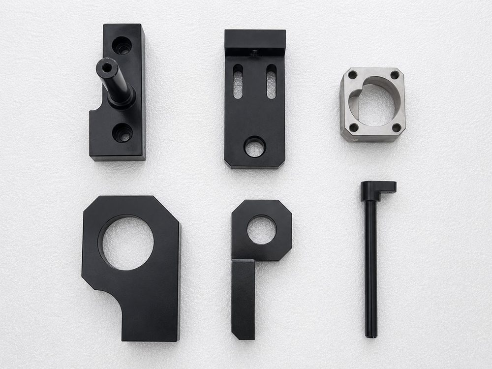
Automation brackets, mounting plates, and fixtures
Scenario 01

Automation brackets, mounting plates, and fixtures

Quantity: 20–200 pcs typical Materials: Aluminum, stainless steel, 45 steel
Typical review points: Hole position and tolerance, flatness requirements, anodizing or plating impact on fit dimensions, assembly clearance and critical mating features.
CNC turned shafts, sleeves, pins, and bushings
Scenario 02

Turned shafts, sleeves, pins, and bushings

Quantity: 50–500 pcs typical Materials: Stainless steel, 45 steel, 440C, brass
Typical review points: Concentricity and runout tolerance, thread fit and class, surface roughness on bearing or sealing surfaces, agreed inspection method for critical diameters.
CNC machined parts with anodizing and surface finishing
Scenario 03

Machined parts with finishing requirements

Quantity: 20–300 pcs typical Processes: Machining, anodizing, plating, heat treatment, marking
Typical review points: Dimensions before and after finishing, dimensional impact of heat treatment, cosmetic surface protection during processing, packaging to prevent contact damage on finished surfaces.
Prototype and first-order custom CNC machined parts
Scenario 04

Prototype or first-order custom parts

Quantity: 1–10 pcs Common need: Feasibility review before committing
Typical review points: Drawing completeness and missing specifications, process feasibility for tight tolerances, material availability and lead time, risk points that could affect the first run.
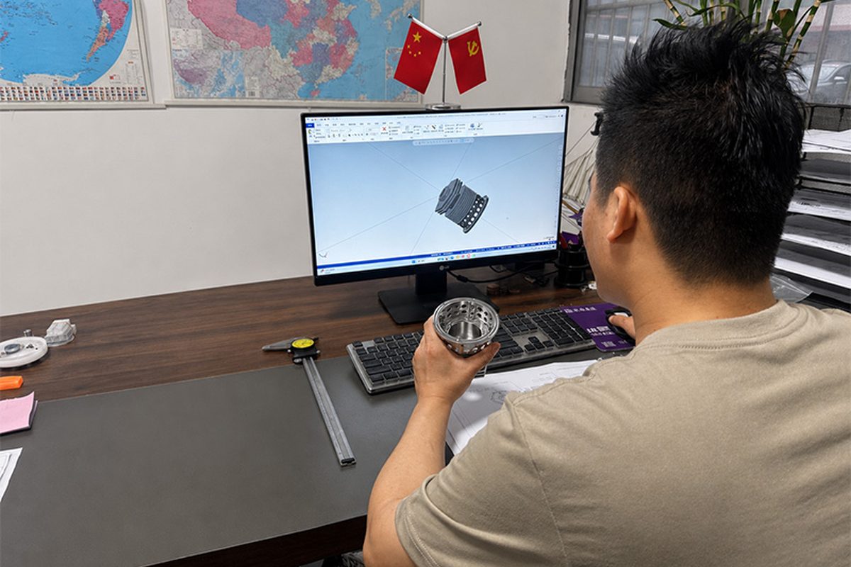
Engineering drawing review with dimensional check at Meili Machining
Before machining starts

What we review before accepting an order

Most problems in custom machining come from unresolved questions at the drawing stage. Before confirming production, we go through these points — not as a bureaucratic checklist, but to avoid rework and delivery disputes later.

  1. Drawing completeness: All required tolerances, surface finish callouts, and reference dimensions present
  2. Tolerance and critical dimensions: Feasibility of tight tolerances with the planned process and material
  3. Datum and inspection method: How critical dimensions will be measured — agreed before production, not after
  4. Material and process feasibility: Grade, condition, and whether the process matches the geometry
  5. Thin-wall or deformation risk: Parts at risk of warping during machining or heat treatment
  6. Threaded holes, inserts, and assembly features: Thread class, insert type, and assembly clearance
  7. Finishing impact on dimensions: Anodizing, plating, or heat treatment effect on final size and fit
  8. Packaging requirements: Whether finished or cosmetic surfaces need separation or protective wrapping
On inspection methods: Many machining disputes come from different inspection methods, not only from machining errors. For critical dimensions, we try to confirm the measuring approach early — before production, not when parts arrive.
Quality & packaging

Inspection, reports,
and delivery preparation

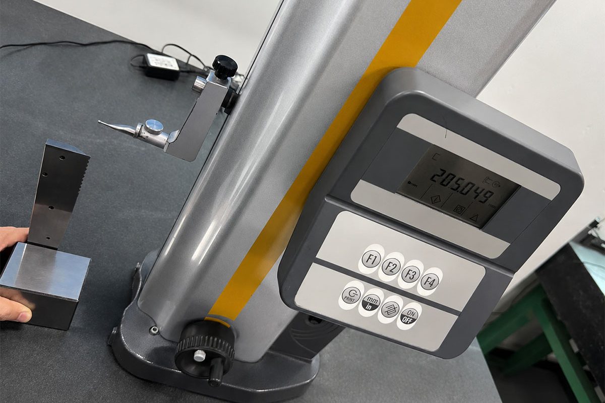
In-house inspection tools cover the majority of dimensional checks. For tight-tolerance or complex geometry requirements, external CMM inspection can be arranged when needed.

Height gauge
Linear dimensions, step heights, datum verification
Optical / profile projector
Profile, radius, and contour verification on projected image
Roughness tester
Ra surface roughness measurement on machined surfaces
CMM (external, on request)
Arranged through partner inspection for complex or critical parts
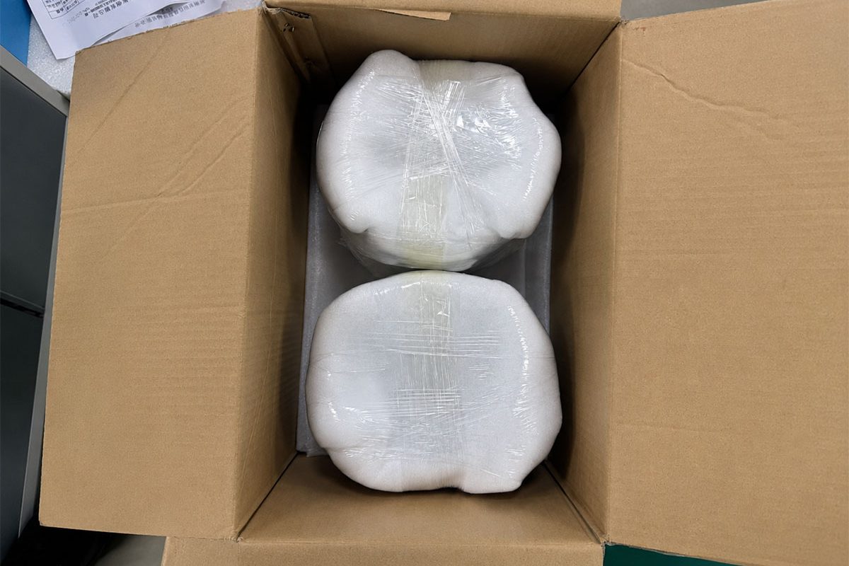
Reporting and packaging: Dimension reports are available on request. First article confirmation can be supported when required. Final inspection is done before shipment. Custom packaging — foam inserts, individual wrapping, separated layers — can be arranged for finished or cosmetic-sensitive parts.
Dimensional inspection with measuring instruments at Meili Machining
Inspection before shipment
Export packaging with foam protection for finished CNC parts
Export-ready packaging
How an RFQ works

From drawing to
confirmed quote

We keep the RFQ process straightforward. Send your drawings with the key requirements — we review and respond with a practical quote, not just a number.

01

Send drawings

Include material, quantity, tolerances, finishing, and inspection requirements. PDF, STEP, DWG, or DXF accepted.

02

Engineering review

We review for process feasibility, risk points, and missing specifications. We may ask a few practical questions before quoting.

03

Quote and lead time

Clear price and delivery timeline. Standard RFQs: after drawing review. Complex parts may take longer after review.

04

Production with checks

First article or in-process checks when required. Key dimensions verified against the drawing during machining.

05

Inspection and shipment

Final inspection, dimension report on request, protective packaging, and export shipment coordination.

Have CNC drawings ready for review?

For standard RFQs, we usually respond after drawing review. For complex parts, we may ask a few engineering questions before quoting.

Common questions

Send STEP or IGES for 3D geometry, PDF or DWG for drawings with tolerances and surface finish callouts. Include material, quantity, and any finishing requirements. If you only have a PDF drawing, that is enough to start the review.
Yes. Single-piece prototypes are accepted. For first orders, we review the drawing carefully for feasibility and risk points before confirming. One-piece orders may have higher unit costs than batch runs, and lead times depend on material availability and current scheduling.
Orders of 1–10 pieces are common for prototypes and first orders. The most comfortable production range is 20–500 pieces per batch, where setup costs are well-distributed and process consistency is easier to maintain. Larger repeat orders can be discussed after the first run.
Yes. Dimension reports are available on request. First article confirmation can be supported when required. For parts needing CMM inspection, we can arrange external CMM reports through our partner inspection services.
Meili Machining uses 3+2 indexed positioning for multi-face and angled-feature work. The B and C axes position and lock the part before three-axis cutting. We review complex geometry and confirm a suitable process route before quoting.