Holes & Bores
What to specify
Nominal diameter plus tolerance, or an ISO fit designation (e.g. H7). Depth and position should also be called out if critical.
What affects the result
Tool size and runout, material hardness, wall thickness, and fixturing rigidity. Deep holes are harder to hold than shallow holes.
Common inspection method
Calibrated plug gauge, bore gauge, or micrometer depending on diameter and tolerance requirement.
Position tolerance for hole patterns should be called out with GD&T if assembly fit depends on it.
Shafts & Pins
What to specify
Outer diameter with tolerance, or ISO fit (e.g. h6, g6). Surface roughness on bearing or sealing surfaces should also be specified.
What affects the result
Shaft length-to-diameter ratio, material, tool pressure, and whether live tooling or OD turning is used. Long slender shafts are more prone to deflection.
Common inspection method
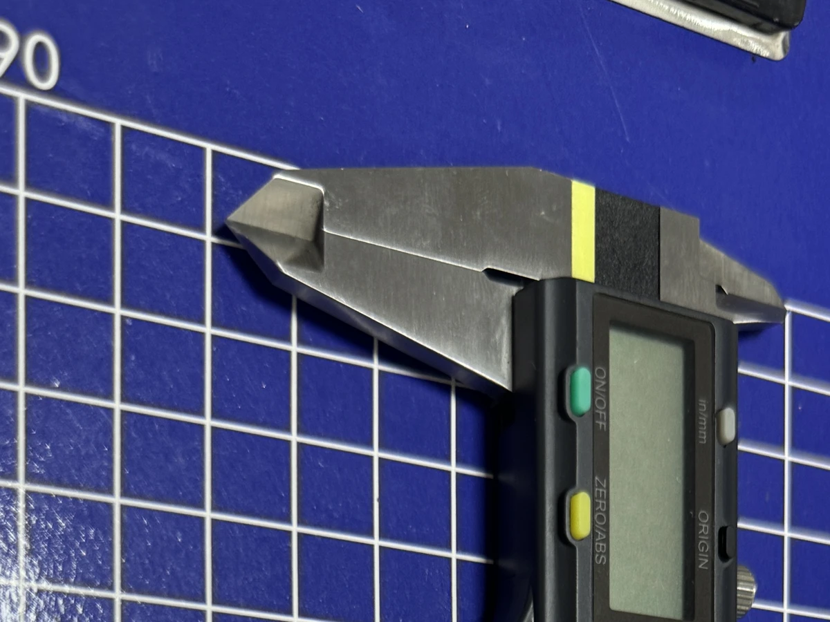
Outside micrometer, ring gauge, or bench-mount indicator for roundness.
Concentricity and runout should be called out where mating or rotating precision is needed.
Threads
What to specify
Thread standard (ISO metric, UNC/UNF), nominal size, pitch, thread class or fit (e.g. 6H/6g), and any special requirements such as length of engagement.
What affects the result
Tap or die quality, material machinability, and whether thread is cut or formed. Blind threads have a minimum depth limit.
Common inspection method
Thread plug gauge (internal) or thread ring gauge (external), matched to the specified thread class.
Incomplete or ambiguous thread callouts are a common cause of nonconformance. Specify fully.
Flatness & Parallelism
What to specify
GD&T flatness symbol with tolerance zone in mm, or parallelism with a datum reference. Title-block tolerance does not control these by default.
What affects the result
Material stress-relief, part clamping during machining, thermal expansion, and thin-wall deflection. Stress in bar stock can cause bow after machining.
Common inspection method
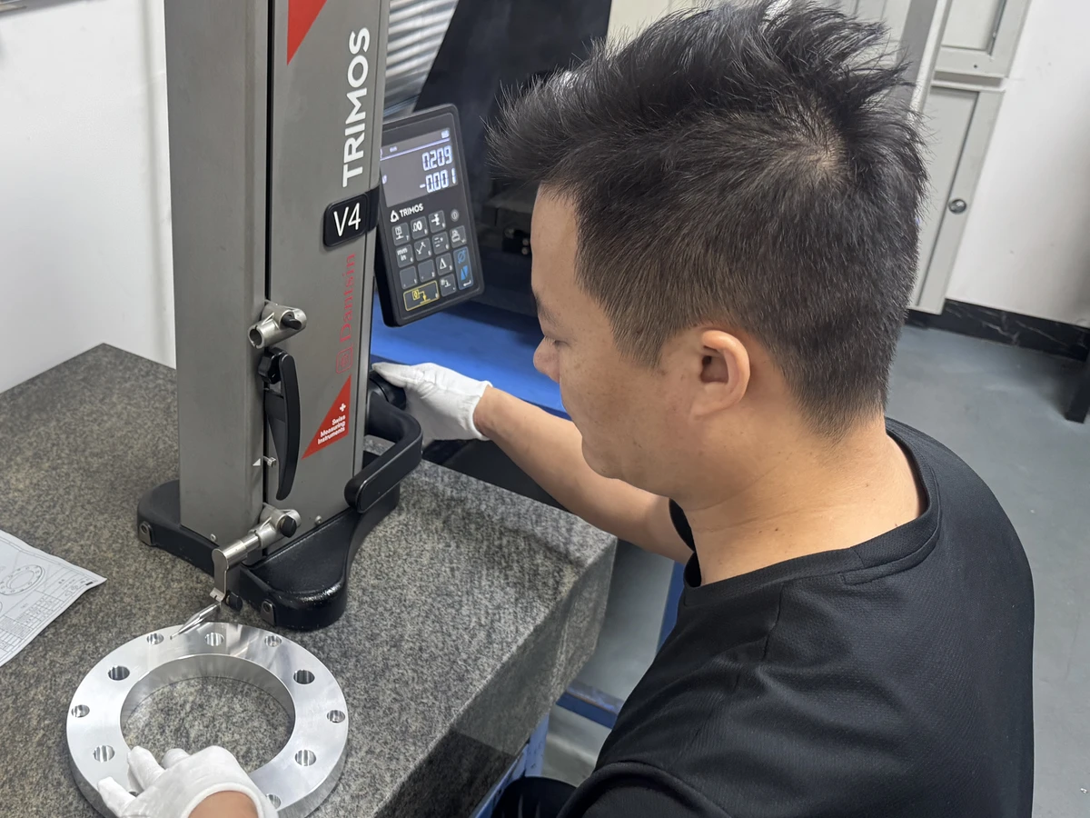
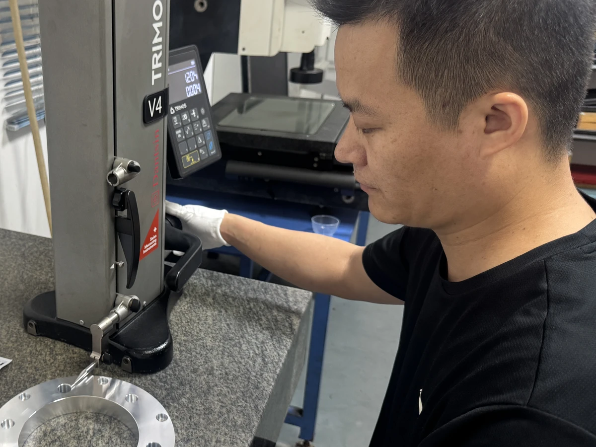
Height gauge on surface plate, indicator sweep, or CMM for complex geometry.
If flatness is functionally important — for sealing, clamping, or mating — call it out explicitly.
Position & GD&T
What to specify
True position callout with datum references for hole patterns, boss locations, or features that must align with mating parts. Include material condition modifier if relevant.
What affects the result
Machine zero accuracy, fixturing repeatability, and cumulative stack-up from earlier operations. Multi-setup parts are harder to hold in position.
Common inspection method
CMM measurement is most reliable for true position. Height gauge and coordinate measurement can be used for simpler cases.
Position callouts require agreed datums and inspection method confirmation before production.
Surface Finish & Roughness
What to specify
Ra value in µm and applicable surface(s). Typical CNC milled surfaces: Ra 1.6–3.2 µm. Ground or fine-turned: Ra 0.4–0.8 µm. Indicate on drawing per ISO 1302.
What affects the result
Tool type, feed rate, cutting speed, material, coolant, and whether a finishing pass is used. Roughness varies by direction of cut.
Common inspection method
Contact profilometer (surface roughness tester). Visual comparison against agreed sample for cosmetic requirements.
Surface finish requirement should be confirmed early — it may affect machining strategy and cost.
 Inspection & Tolerance