- A press fit needs the shaft to be larger than the hole across the whole tolerance range: either an H hole with a plus shaft such as p6 or r6, or a minus hole such as P7 with an h shaft. H7/h6 or H7/h7 will not do it.
- Slip fits (H7/g6, H7/h6) always have clearance; transition fits (H7/k6, H7/n6) may be loose or tight.
- On the small pins and bushings we fit, about 0.01 mm interference is usually enough. Much more makes assembly hard.
- Check the minimum and maximum interference before you release a drawing. It takes a minute and saves a batch.
What is press fit tolerance?
A press fit, also called an interference fit, is a joint where the shaft or pin is slightly larger than the hole, so it has to be pressed in and is held by friction. Press fit tolerance is the pair of tolerance classes on the hole and the shaft, written like H7/p6, chosen so that even the smallest shaft in the hole's largest size still has interference. The classes are defined in ISO 286[1].
Clearance, transition and interference fits
With the common hole-basis system, the hole is H (its lower limit is the nominal size) and the shaft letter decides the fit. These are the limit deviations at Ø10 mm[2]:
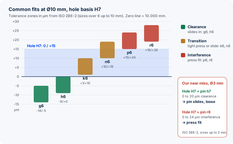
| Fit (Ø10 mm) | Hole H7 | Shaft | Result | Type |
|---|---|---|---|---|
| H7/g6 | 0 / +15 µm | −5 / −14 µm | 5 to 29 µm clearance | Clearance (slip) |
| H7/h6 | 0 / +15 µm | 0 / −9 µm | 0 to 24 µm clearance | Clearance (locating) |
| H7/k6 | 0 / +15 µm | +1 / +10 µm | 10 µm interference to 14 µm clearance | Transition |
| H7/n6 | 0 / +15 µm | +10 / +19 µm | 19 µm interference to 5 µm clearance | Transition |
| H7/p6 | 0 / +15 µm | +15 / +24 µm | 0 to 24 µm interference | Interference (press) |
| H7/r6 | 0 / +15 µm | +19 / +28 µm | 4 to 28 µm interference | Interference (press) |
Values from ISO 286-2 for sizes over 6 up to 10 mm. At other sizes the numbers change: for example, over 18 up to 30 mm, H7 is 0/+21 µm and p6 is +22/+35 µm, giving 1 to 35 µm interference.
The fits we see most on drawings
Across the automation and robot parts we machine, the same classes come up again and again:
- Holes: H7, H6 and H8 by far the most, then G7 and G6.
- Shafts and pins: g6, g7, h6, h7. Locating pins are mostly g6 or h6.
- Bearing seats: K6, K7, N6, N7, and P6 to P9, plus combinations such as N6 and K7 on the same part.
We have machined all of them. The class itself is rarely the problem. The problem is a hole class and a shaft class that do not give the fit the designer had in mind.
The H7/h7 pin we nearly shipped loose
On a part for an automation customer, the drawing called for Ø3 mm H7 holes and Ø3 mm h7 pins. In use, the pins had to be tight. We machined to the drawing, and the pins slid in.
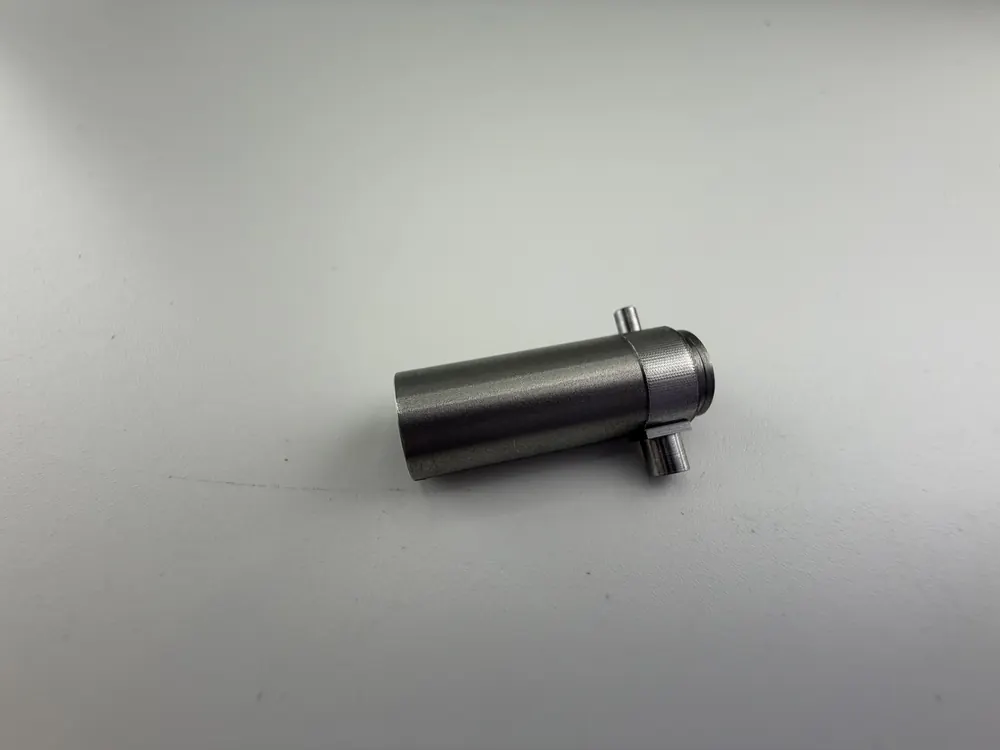
The numbers explain why. At 3 mm, H7 is 0/+10 µm and h7 is 0/−10 µm[2]: the pin can never be larger than the hole, so the fit has 0 to 20 µm of clearance. For a tight pin, the hole stays at H7 and the pin needs a plus deviation. We suggested changing the pins to r8 (+10/+24 µm at 3 mm), which gives 0 to 24 µm of interference with the same holes. The customer agreed, we replaced all the pins we had bought with r8 pins, and the parts went out with tight pins. They are the shafts in the photo at the top of this article.
Some customers get the tight fit the other way round: the pin stays at h and the hole is made minus, for example N7 or P7. That is the shaft-basis system, and it is common when standard h-tolerance pins are bought in. It works, but check the numbers here too. At 3 mm[2]:
| Fit (Ø3 mm) | Hole | Pin | Result | Type |
|---|---|---|---|---|
| H7/h7 | 0 / +10 µm | 0 / −10 µm | 0 to 20 µm clearance | Clearance: the loose pins |
| H7/r8 | 0 / +10 µm | +10 / +24 µm | 0 to 24 µm interference | Interference: our fix |
| N7/h6 | −4 / −14 µm | 0 / −6 µm | 2 µm clearance to 14 µm interference | Transition: usually tight, not always |
| P7/h6 | −6 / −16 µm | 0 / −6 µm | 0 to 16 µm interference | Interference |
The lesson for us was to check every fit pair against how the part is used before machining, not after. The lesson for designers: H7/h7 looks precise, but it is a clearance fit, and N7 makes a pin tight most of the time, not every time.
How much interference is enough?
On the small pins and bushings we fit, about 0.01 mm of interference is usually enough for a tight fit. Much more than that and the parts become hard to assemble, and a thin housing can crack or a pin can gall on the way in.
That is a rule of thumb for small parts, not a design rule. Larger diameters, thin walls, soft or plastic housings, and parts that change temperature in use all need the fit chosen for the job. Always check both ends of the range: the minimum interference (largest hole, smallest shaft) must still hold, and the maximum must still assemble.
Fits at Meili
- H6, H7, H8 holes and g6 to p6 shafts machined regularly
- Bearing seats to K, N and P classes
- Pins pressed in-house and parts delivered assembled
- Go/no-go gauges, CMM, bore gauges; air gauges on request
How we machine and check H7 bores
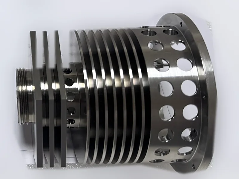
There is no single way to make an H7 hole. We first look at the material, then the diameter and depth, and choose the tool and the process from that. Many H7 holes are machined directly on our CNC machines. Deeper or more difficult ones are reamed or bored, and some features go to EDM.
| How a fit is checked | When we use it |
|---|---|
| Go/no-go gauges | Most automation parts, where the fit is what matters |
| CMM plus three-point bore gauge | More demanding cylindrical features, size and roundness |
| Air gauge | A few customers who specify it |
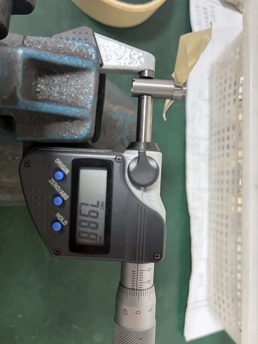
The first article is always measured. In a batch we sample during production, and outgoing parts are sampled to the customer's requirement. If you need a particular method, tell us and we will measure that way. More on measurement in our tight tolerance guide.
Getting the fit right on your drawing
- Decide the function first: slides, locates, or holds. That picks clearance, transition, or interference.
- Write the pair, such as H7/p6, or give both limits. A hole class alone does not define a fit.
- Pick one system. Hole basis (H hole, the shaft letter sets the fit) suits machined pins and shafts; shaft basis (h pin, the hole letter sets the fit) suits bought-in standard pins.
- Calculate the minimum and maximum clearance or interference from ISO 286 for your size. If the minimum interference is below zero, it is not a guaranteed press fit.
- Allow for coatings. Anodizing and plating change sizes; see how much anodizing grows a part.
- Ask us. Send the drawing and tell us how the parts go together. We check the fits before we machine.
Not sure your fits will work?
Send the drawing and tell us which parts must slide, locate, or press. We check every fit pair and quote within 24 hours.
Send your drawingFAQ
What is press fit tolerance?
A press fit, or interference fit, is one where the shaft or pin is slightly larger than the hole, so it has to be pressed in and holds by friction. The press fit tolerance is the pair of tolerance classes on the hole and the shaft, for example H7/p6, chosen so that every part in the tolerance range still has interference.
What is the difference between clearance, transition and interference fits?
In a clearance fit the shaft is always smaller than the hole and slides in (for example H7/g6 or H7/h6). In an interference fit the shaft is always larger and must be pressed (H7/p6, H7/r6). A transition fit can be either, depending on where the actual sizes fall (H7/k6, H7/n6).
Is H7/h7 a press fit?
No. With an H7 hole and an h7 shaft, the shaft can never be larger than the hole, so the fit is a clearance fit. At 3 mm it gives 0 to 20 µm of clearance. We once machined Ø3 H7 holes for h7 pins on a part that needed a tight pin; the pins were loose, and we changed them to r8.
Can I make a press fit with a standard h pin?
Yes, by making the hole minus instead, which is the shaft-basis system. At 3 mm, a P7 hole with an h6 pin gives 0 to 16 µm of interference. An N7 hole is a transition fit: usually tight, but at the extremes of the tolerances it can have up to 2 µm of clearance.
How much interference do I need for a press fit?
On the small pins and bushings we fit, about 0.01 mm of interference is usually enough for a tight fit. Much more than that makes the parts hard to assemble. Larger diameters, thin housings, and different materials change the answer, so choose the fit by function and check the minimum and maximum interference.
What is H7 tolerance?
H7 is the most common hole tolerance class. The lower limit is the nominal size and the upper limit adds the IT7 tolerance: for example 0/+15 µm for sizes over 6 up to 10 mm, and 0/+21 µm over 18 up to 30 mm, per ISO 286-2.
What is a slip fit tolerance?
A slip or sliding fit is a clearance fit where the parts slide together by hand with very little play. H7/g6 and H7/h6 are the usual choices; at 10 mm, H7/g6 gives 5 to 29 µm of clearance and H7/h6 gives 0 to 24 µm.
How do you check H7 holes?
For most automation parts the fit is checked with go/no-go gauges. For more demanding cylindrical features we combine CMM and a three-point bore gauge, and a few customers ask for air gauges. The first article is always measured, batches are sampled during production, and outgoing parts are sampled to the customer's requirement.

Raymond Liang
Co-founder and Technical Sales Manager at Meili Machining in Dongguan. Raymond spent ten years on CNC turning and milling before co-founding Meili in 2017, and he still reviews drawings and plans the setups for difficult parts himself.
Sources
- ISO 286-1:2010, Geometrical product specifications (GPS) — ISO code system for tolerances on linear sizes — Part 1: Basis of tolerances, deviations and fits. www.iso.org
- ISO 286-2:2010, Part 2: Tables of standard tolerance classes and limit deviations for holes and shafts. www.iso.org
How this article was made: the fits customers use, how we machine and check bores, the 0.01 mm rule of thumb, and the H7/h7 pin case come from Raymond Liang's first-hand experience. Limit deviations are taken from ISO 286-2. The text was drafted with AI-assisted editing and reviewed by Raymond before publishing.